Form Auto
An Automated Part Removal System for Form 3 SLA Printers
Designed at Formlabs during 2021-2022
Overview
During my year working on Form Auto from July 2021 to August 2022, I was one of three mechanical engineers who helped take this product from a vague “What does the next generation of printer automation look like” to the final product.
This included the early concepts and prototypes of competing architectures, high level mechanism brainstorming, detailed part design, part and assembly drawings, and onboarding of our contract manufacturer.
I personally think that Form Auto contains some of the most fun mechanisms I have been able to put onto a production product. Please read more details about it below.
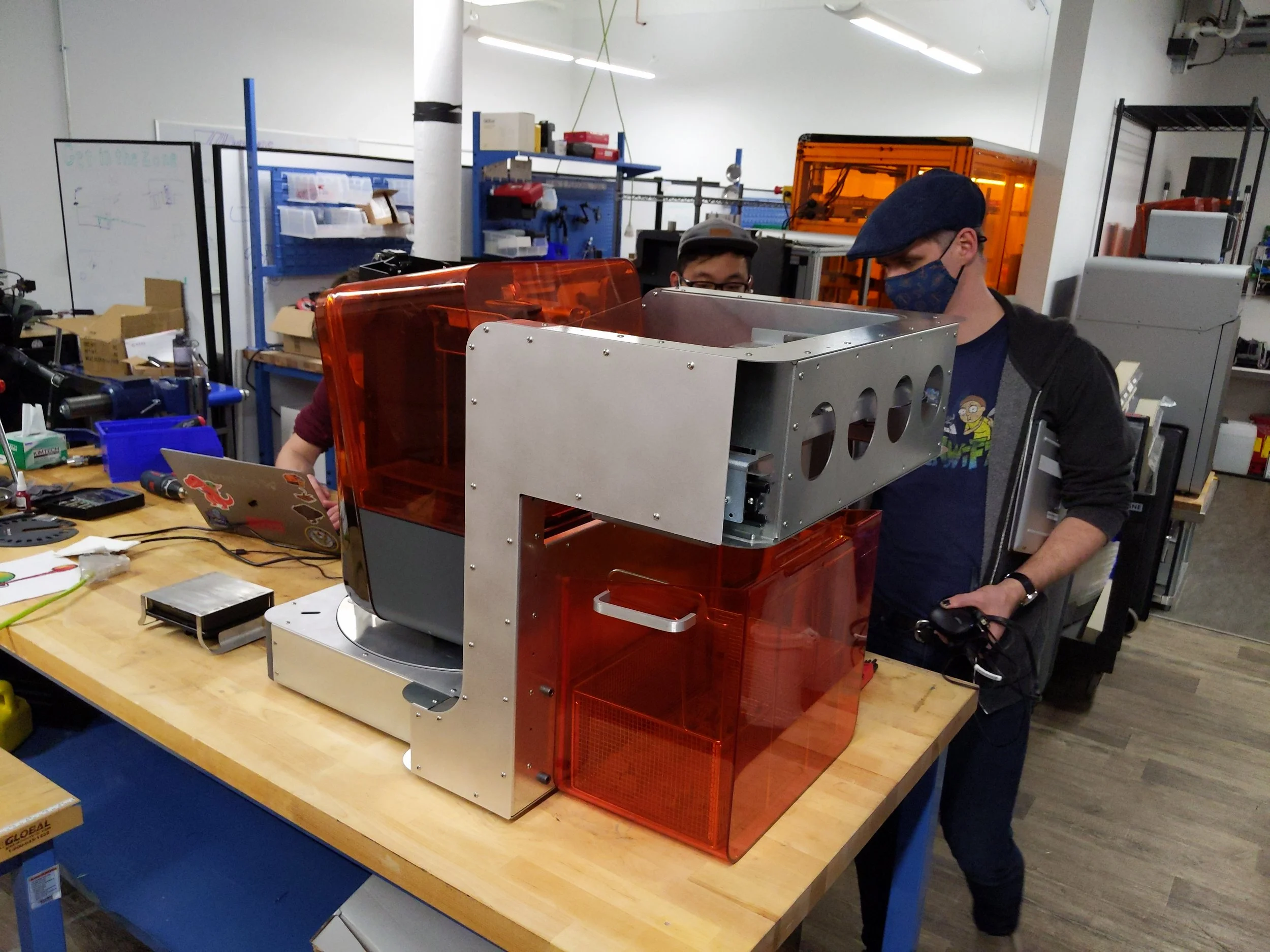
What I Owned
I was the sole mechE responsible for the part removal subsystem. This includes all of the highlighted parts shown. At a high level, my job was to take an open printer with parts at a known location, somehow remove those parts, and drop them off at the collection bucket.
The design of this system had some particularly interesting constraints.
Form 3 had already been released, and the interaction points were not designed with automation in mind
There was a clear-cut goal to automate the printer for less than the cost of the printer, greatly limiting the actuation mechanism options
Anything designed to catch the parts had to be as thin as possible, as every additional mm of thickness would reduce the maximum part height that would be compatible with the system
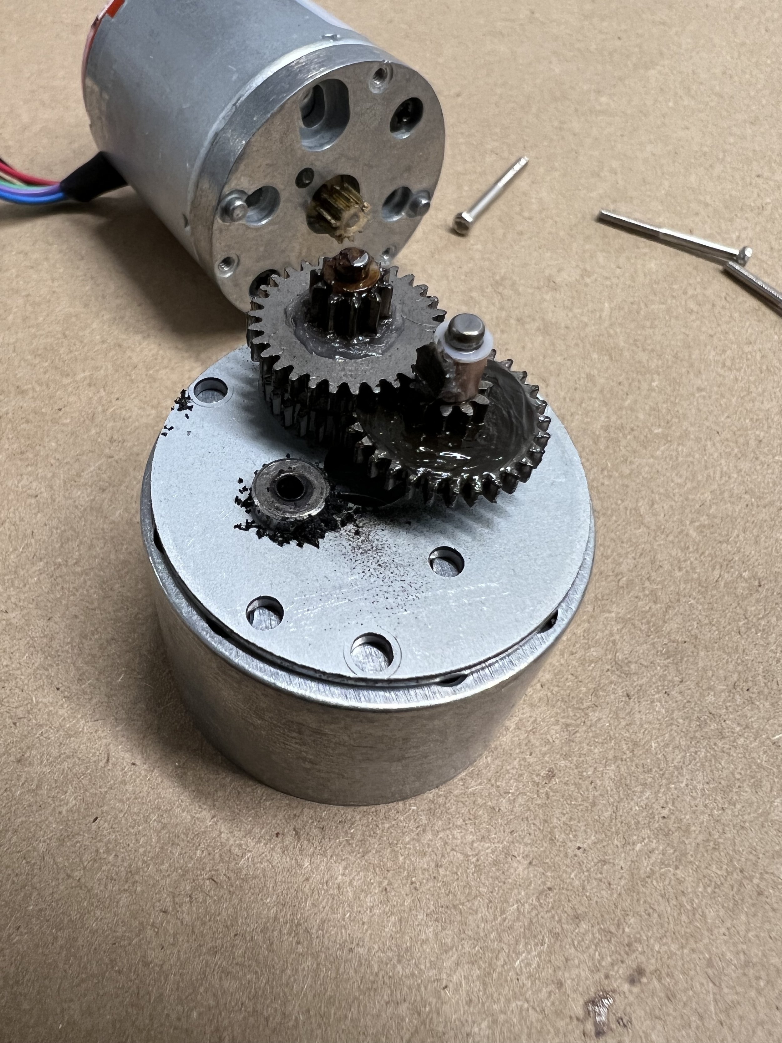
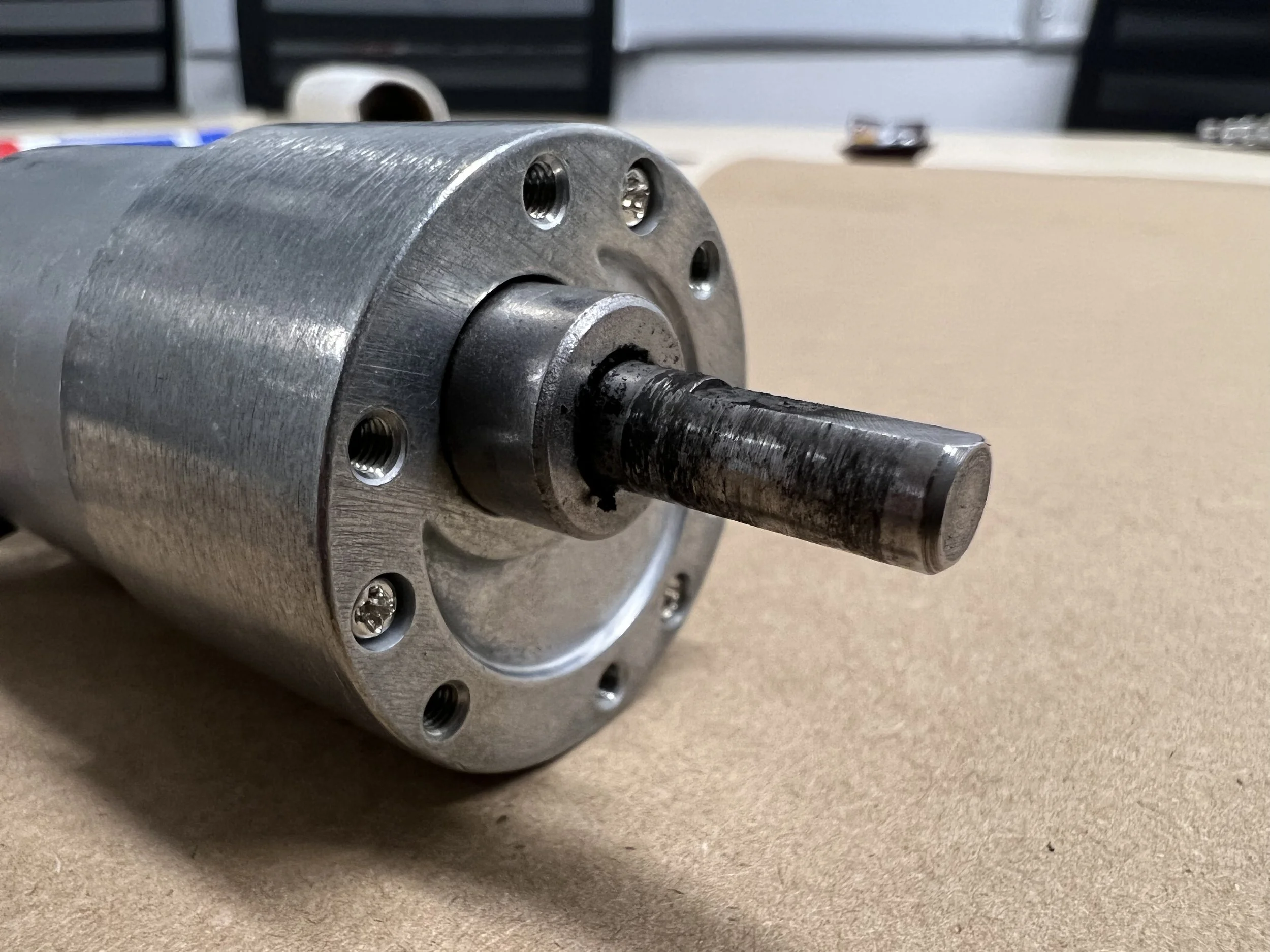
There were several unique challenges to making this system work, but by far my proudest achievement with this product was accomplishing every single required motion for part removal with a single, low cost geared DC motor.
Basics of Operation
Fundamentally, there are two flavors of motion required for the part removal system to work.
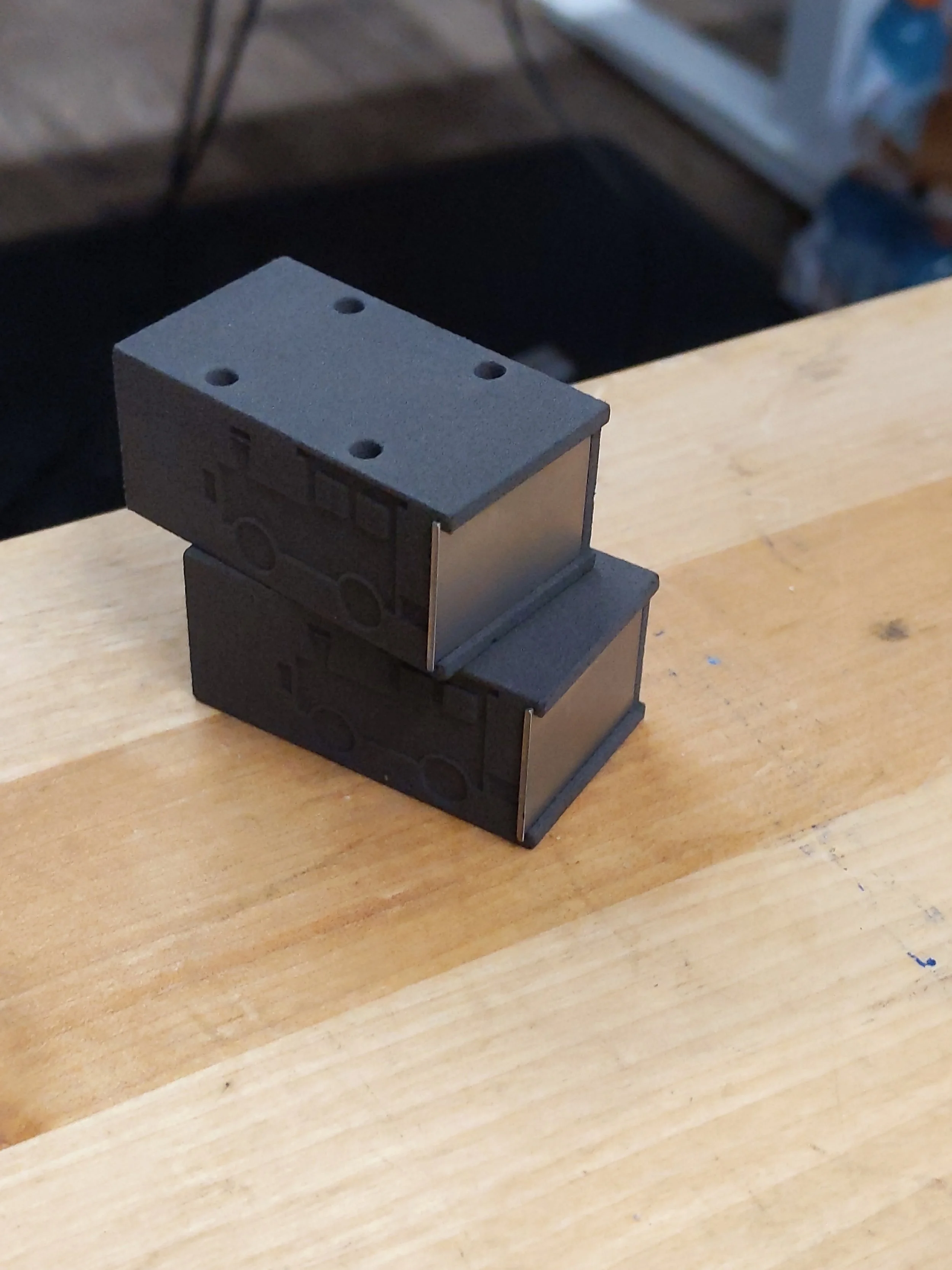
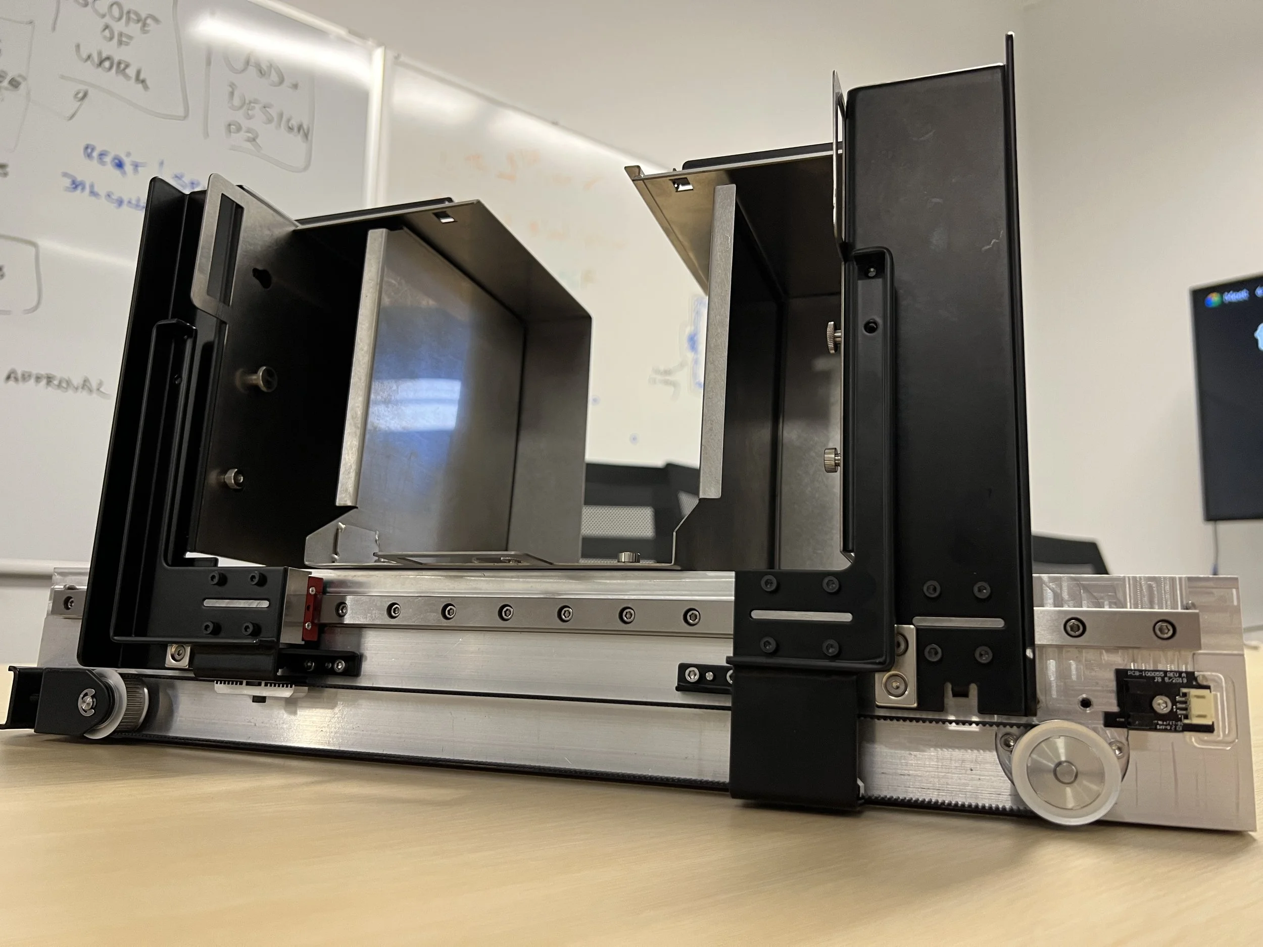
First, two basket-halves come in to surround the part. This is necessary because part removal is a very non-deterministic process, and surrounding the part on all 4 sides is a must. When the part removal system is over the part storage bucket, the two basket-halves open, dropping the printed parts out the bottom.
Second, two small knubs are required to actuate the build platform and pop the parts off. Since the build platform was never designed with automation in mind, they have a somewhat unusual and organic shape, but they work consistently.
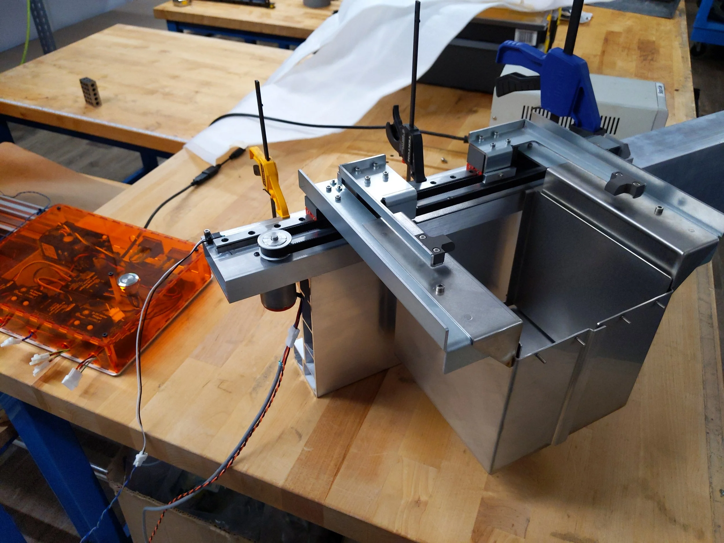
Putting it All On One Motor
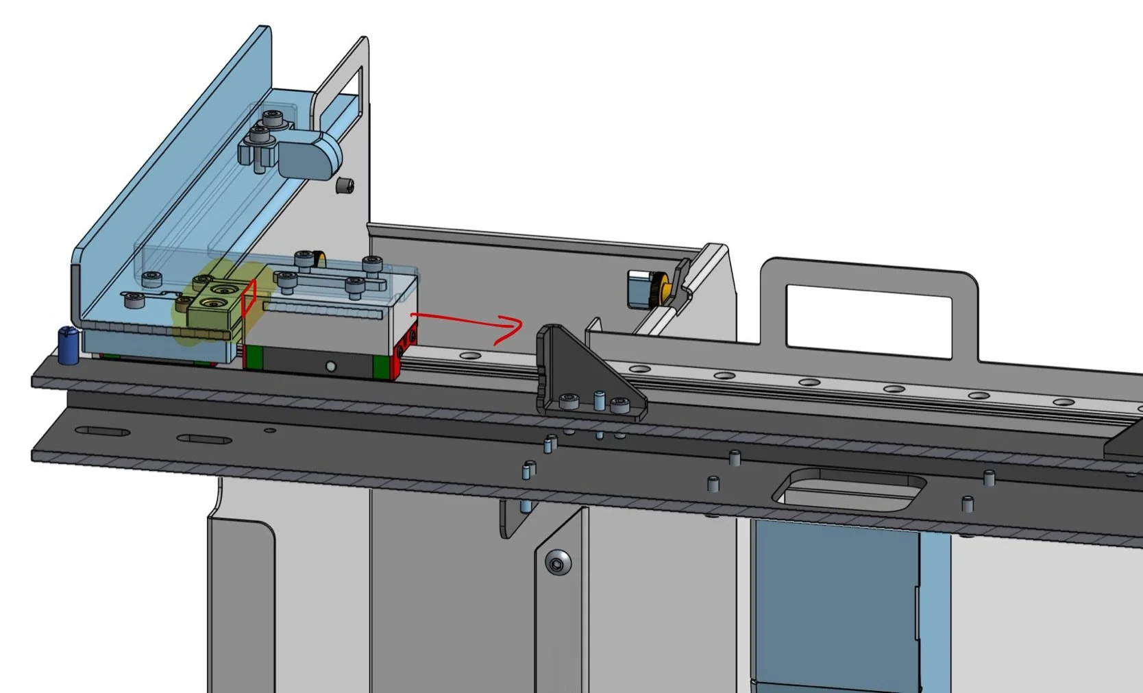
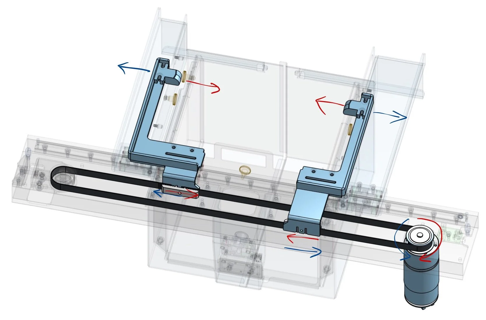
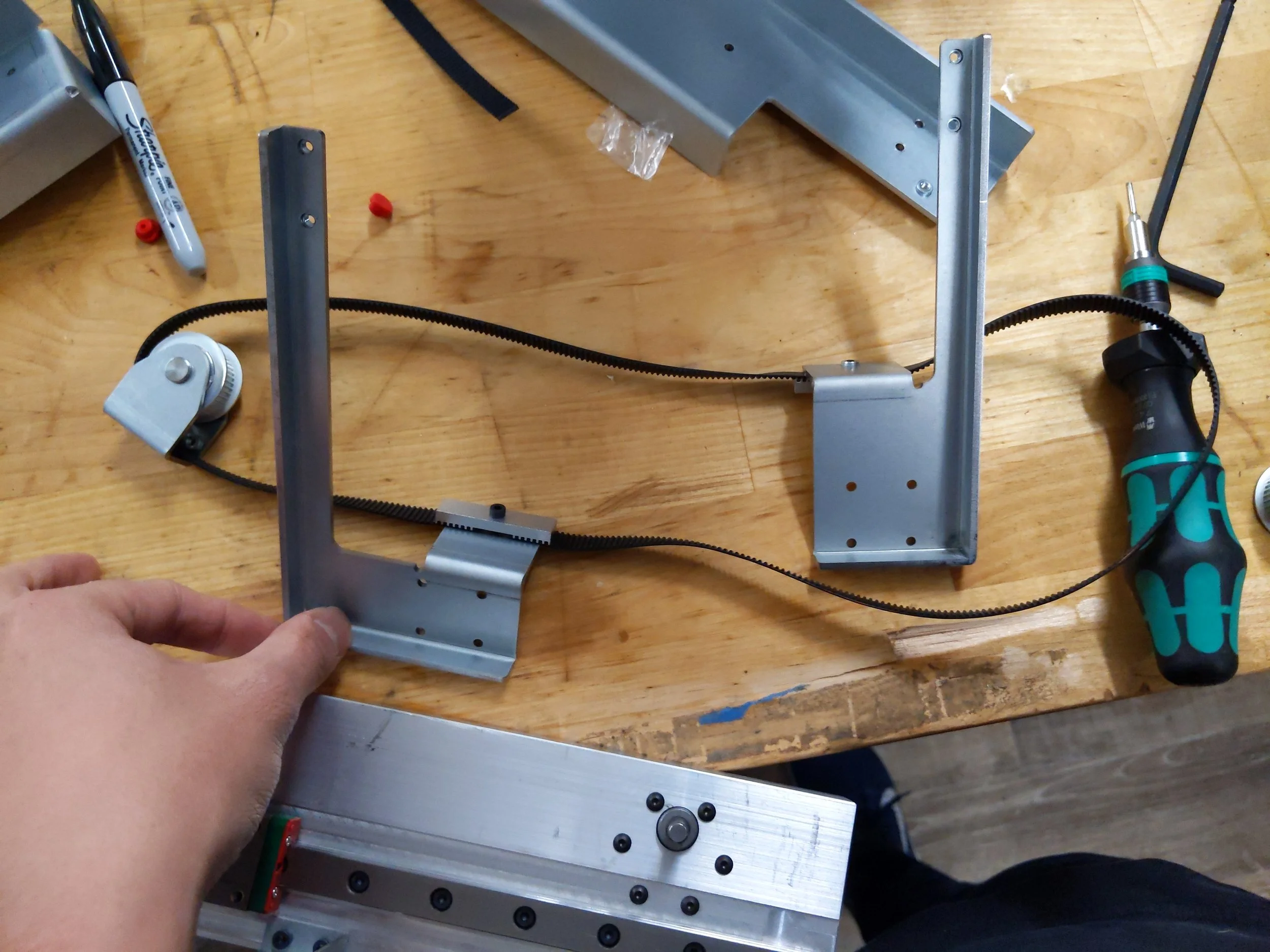
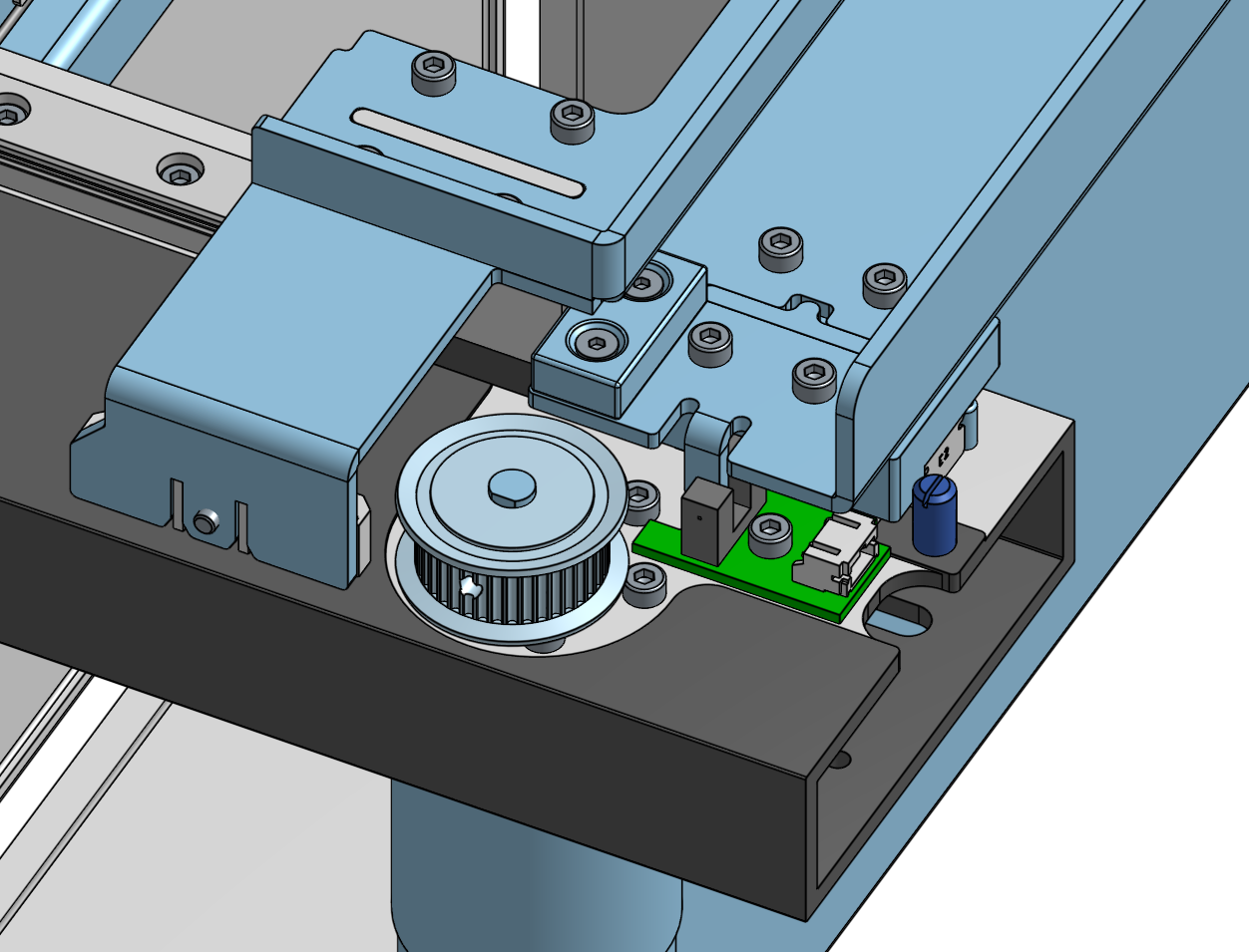
Using a well placed magnetic hardstop, I was able to accomplish all the required motions using one motor. Using a pulley system, sheet metal brackets for the actuation points were tied to opposite sides of the pulley. This guaranteed synchronized relative motion.
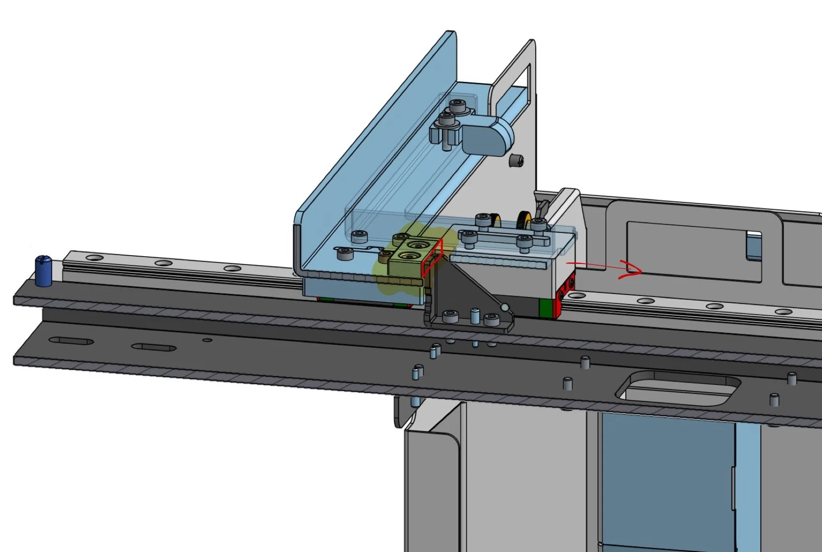
Now comes the fun trick. The set of sheet metal arms that hold the catch basket can be magnetically coupled to the arms that mount the actuation points. By homing the system in the open position, I guarantee that the basket arms magnetize to a steel block placed below the actuation arms.
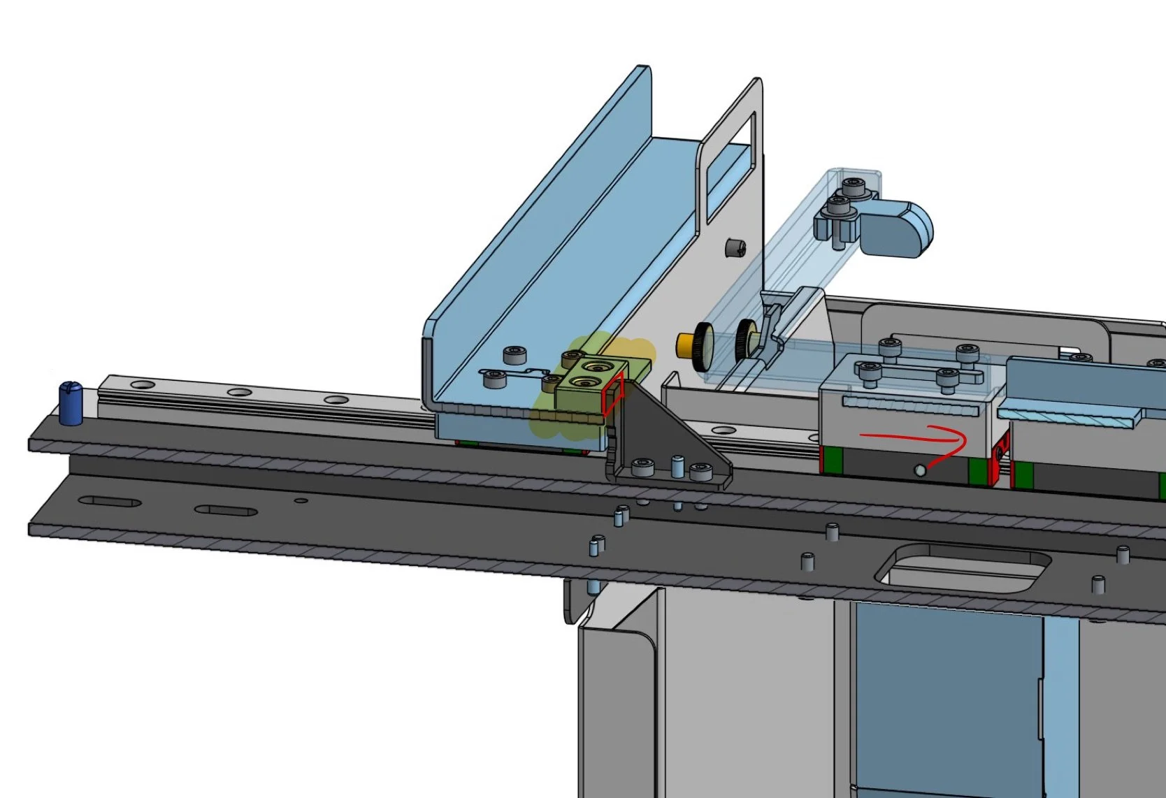
Once the baskets are closed, the basket arms hit a steel hardstop, fixing the location of the baskets while the actuation arms get to continue moving freely.
The series of 3 images below show the three states clearly:
Basket arms magnetized to actuation arms
Basket arms hit hardstop
Actuation arms continue moving
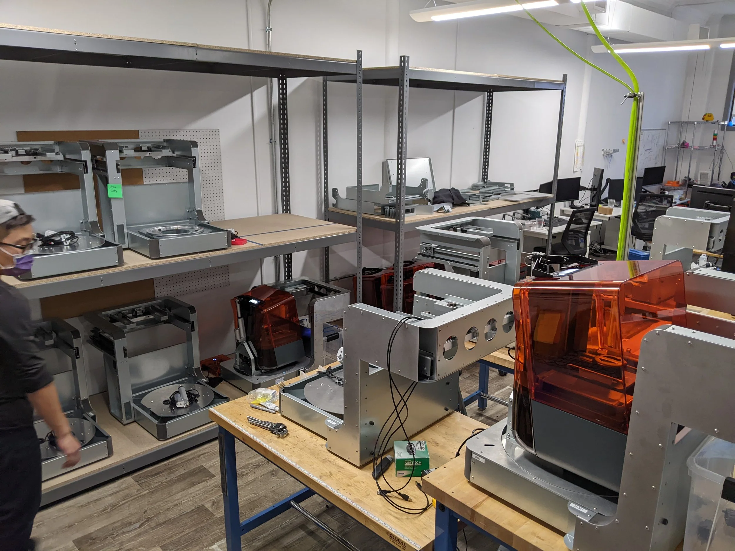
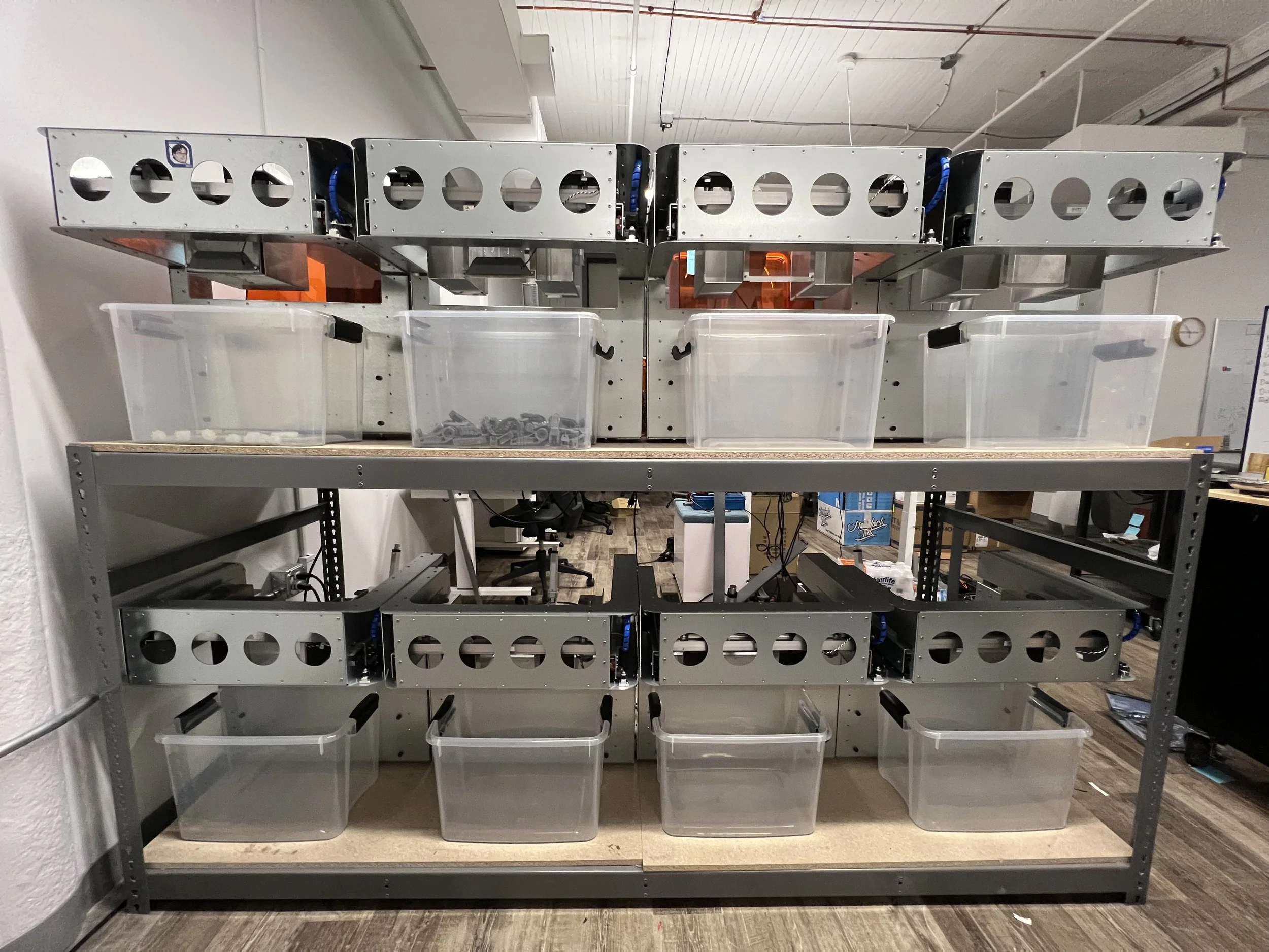
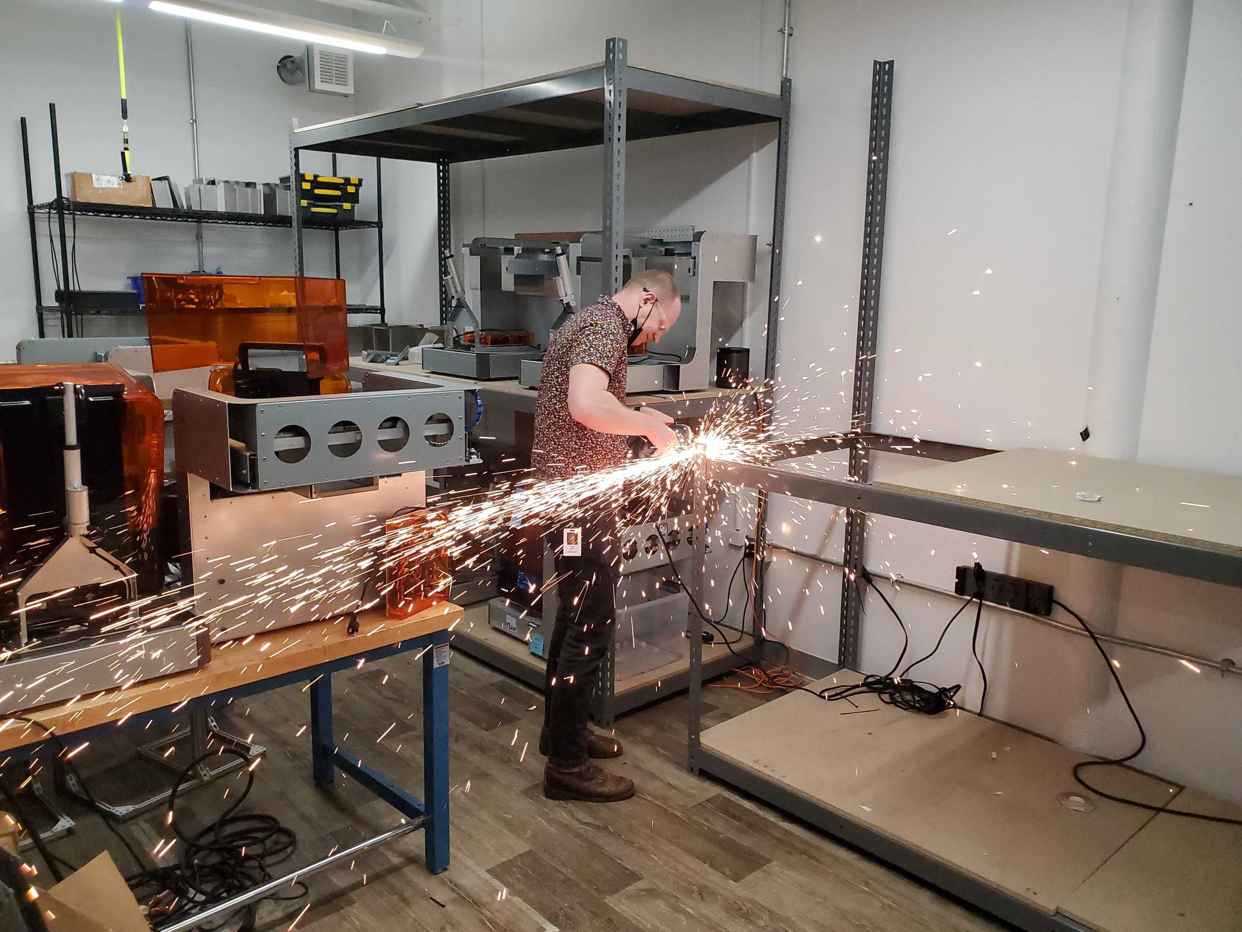
An early lifetime test rig for the part removal subsystem. These lived in the same office space as us before the repeated popping noises relegated the jig to the cursed basement you see here.
Fun Design Details
There are many small touches on this system worth pointing out, so the section below is a grab-bag of miscellaneous details that I am happy with.
Note: The formatting of the section below is broken on mobile view, resulting in mismatched image captions. Unfortunately, my web dev days are behind me and I do not possess the mental fortitude required to fix it.
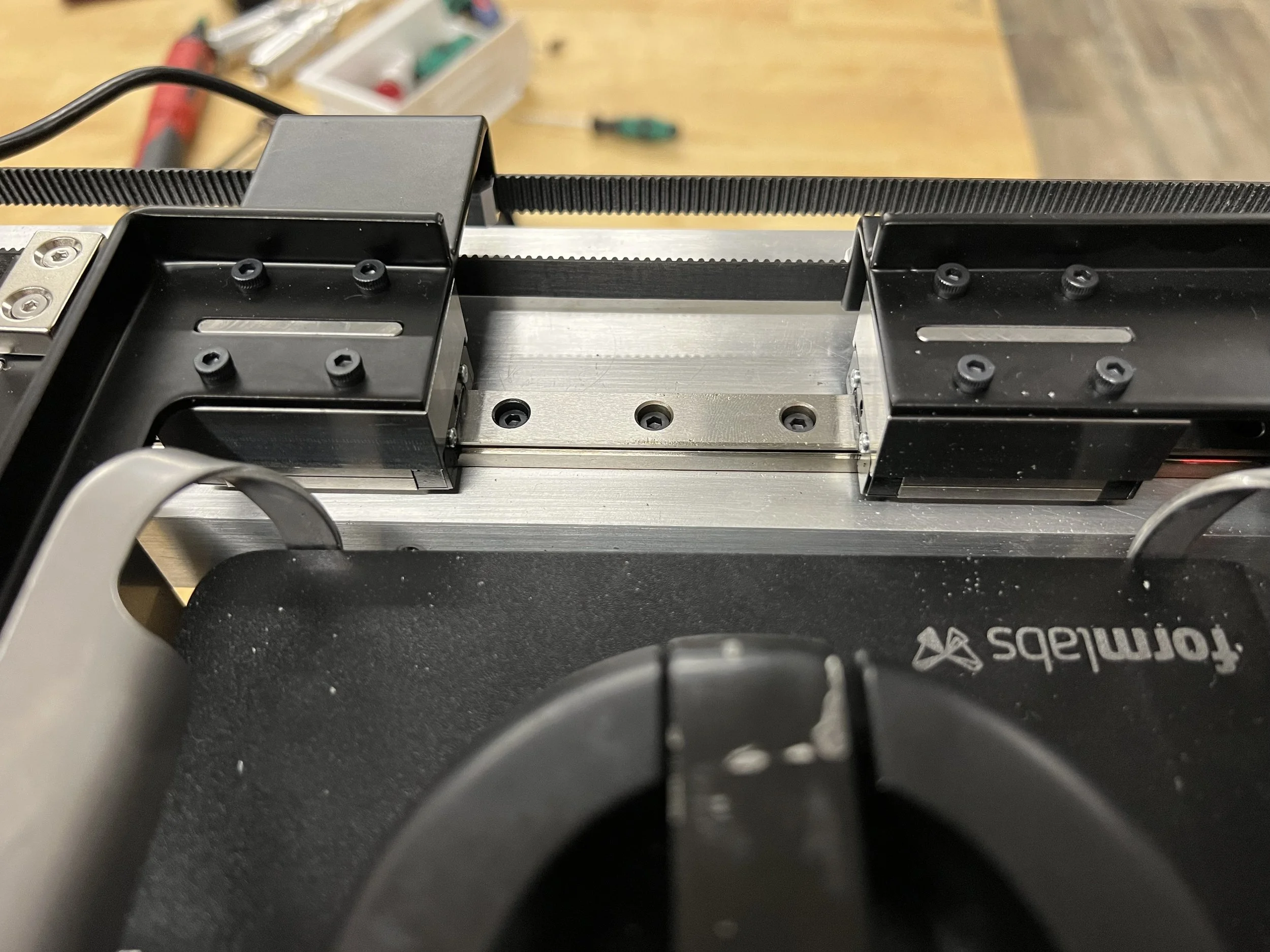
Rather than using a belt loop, I designed the system with two equal lengths of open belts.
This way, the pulley clamps complete the loop and perfectly set the spacing of all the pulley loop components automatically, reducing the assembly error risk and creating an obvious visual check for IPQC.
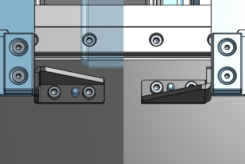
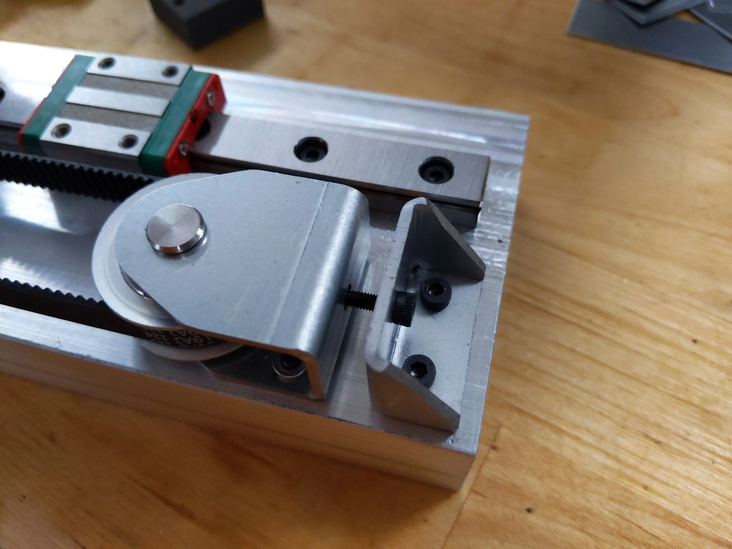
An asymmetric pin was added to poka-yoke the hardstops.
This removes a BOM line by removing the need for left and right handed version, preserves the sheet metal simplicity, and makes it significantly harder to assemble incorrectly.
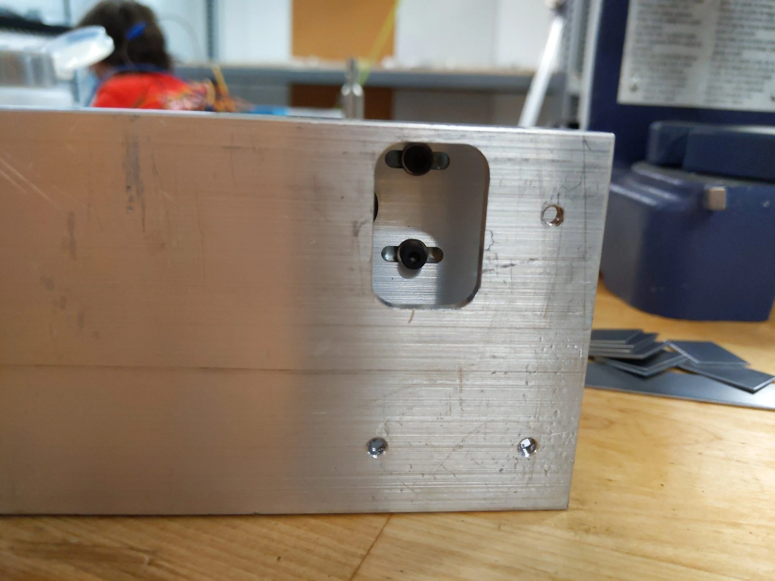
The belt tensioning system has a jig built right into it. A screw goes through a bracket at the end of the extrusion and threads directly into the sheet metal clevis mount.
Once the screw is tightened to a target tension as verified by a sonic tension meter, two additional screws come in from the bottom to fully lock down the system and prevent loosening over time.
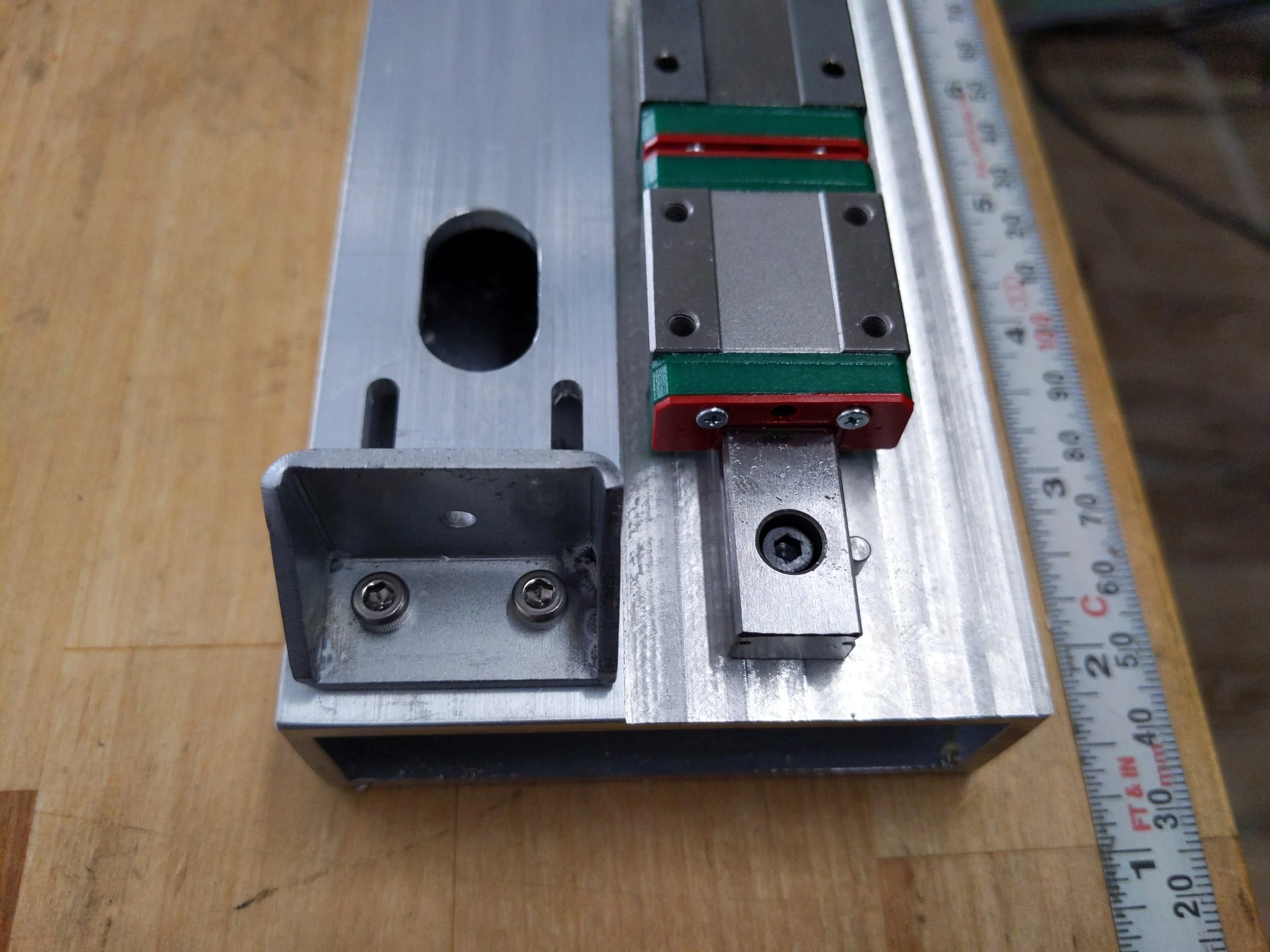
The shock load on the actuation points can be quite severe, which puts a serious moment on the mounting interface between the basket arms and linear blocks.
Rather than relying on screws to supply sufficient friction in shear, a positive slot was added to the mounting blocks, and a matching negative slot in the sheet metal was added and masked from powdercoating to achieve a tight fit.
Homing of the entire system happens using an optical limit switch. The flag for this switch is a simple bent flange hanging off the end of the basket arms, reducing the need for another part.
Choosing this homing position allowed us to magnetize the basket arms to the actuation arms at the start of every homing routine.
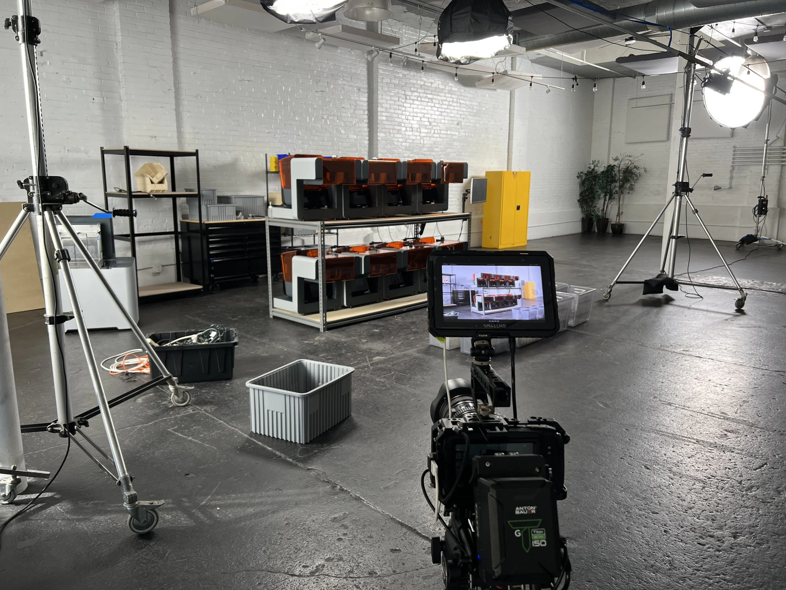
Gallery
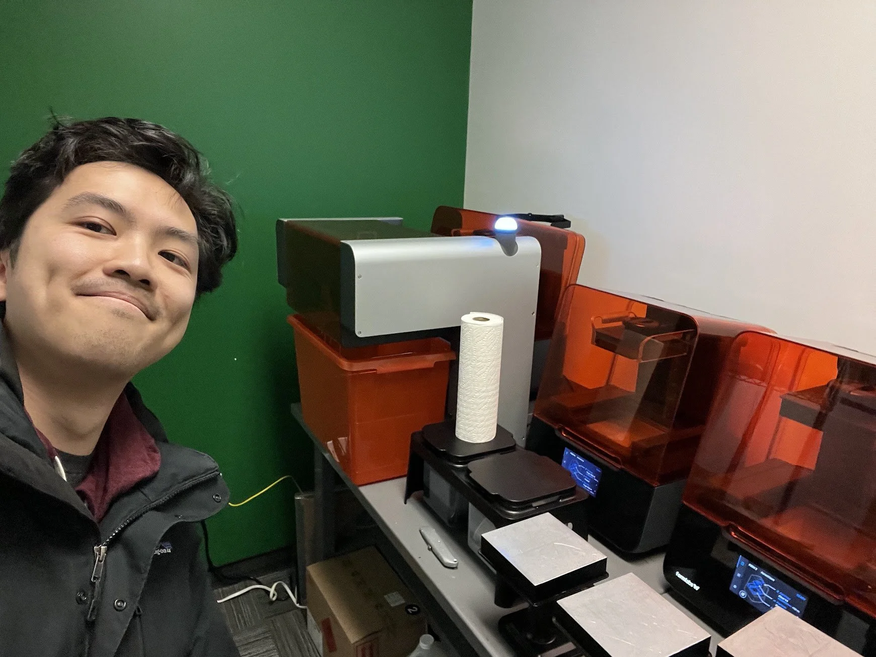
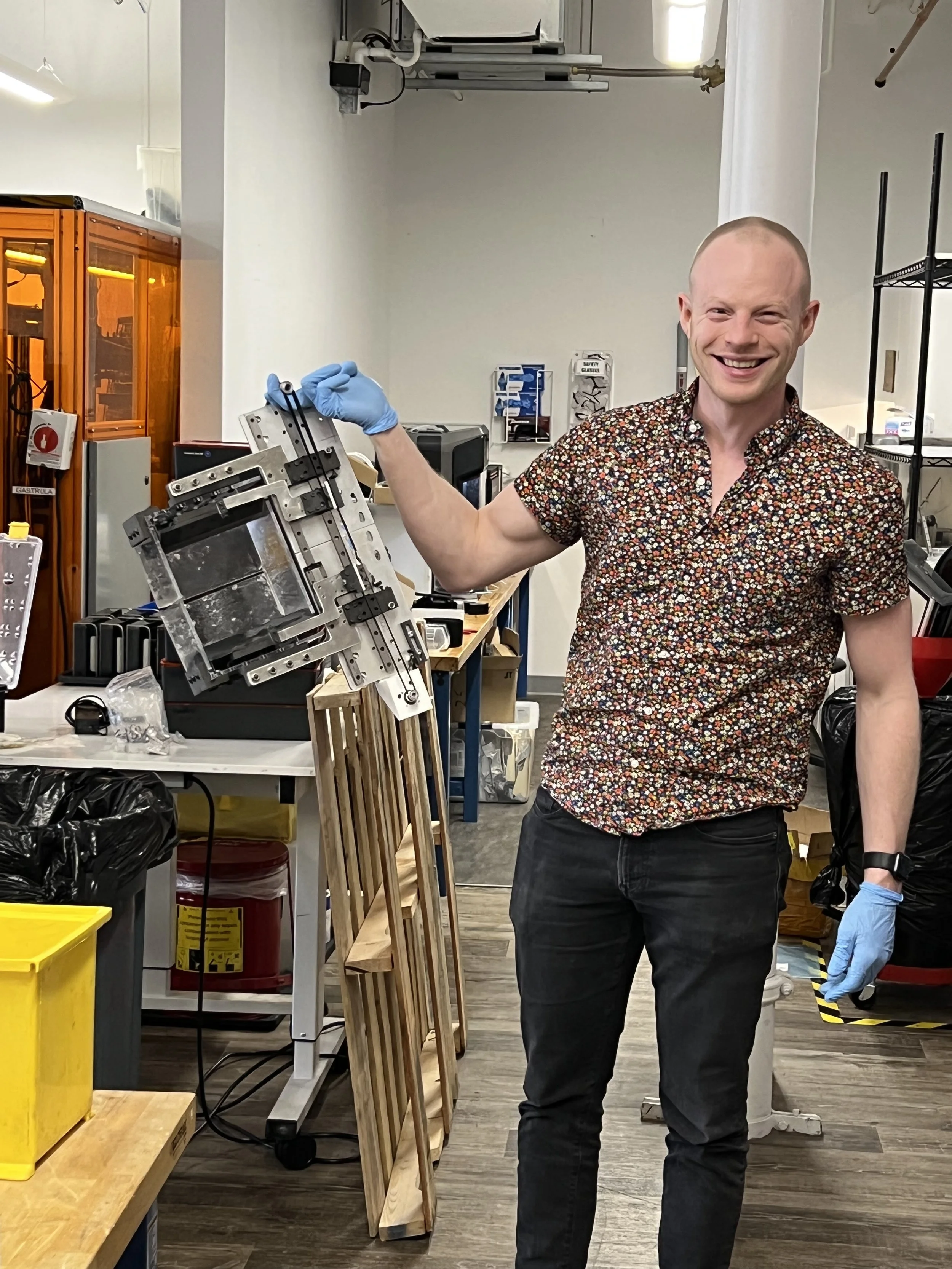
Here is me excitedly taking a photo of a Form Auto the first time I saw one in the wild. This one was located at Giatec in Ottawa, Canada.
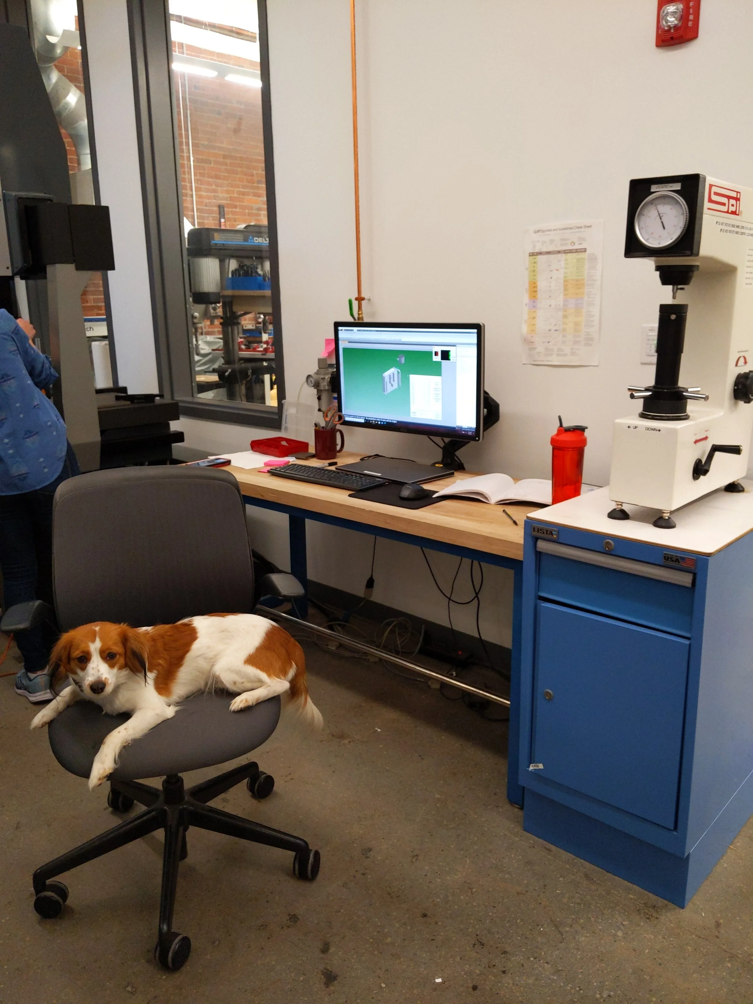
Below are miscellaneous other images from the program’s lifecycle. Thank you for reading about this program!